Ultrawave LRT
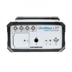
The UltraWave LRT uses guided wave technology and excites low-frequency ultrasonic waves that travel lengthwise over tens of meters along a pipe, detecting wall thickness variations. The system is ideal to screen in-service pipes and pipelines, and to inspect limited access pipes from a single inspection position. It includes advanced software, acquisition unit, touch screen laptop, and compact probes with bands and bladders.
Pipe Inspection with Guided Waves
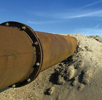
Offering the capacity to screen in-service pipes and pipeline over long distances, guided wave inspection is used to localize areas of concern on above-ground conventional structures and for advanced applications such as buried, insulated, coated, and vertical pipes. This technology also detects corrosion at supports, clamps, and pipe racks.
Guided wave technology can perform inspections on pipes with limited access. It pinpoints locations that require further inspection, avoiding unnecessary excavation, coating removal, or scaffolding, if no flaw is detected. The use of this technology helps provide a significant reduction in operating costs and is considered an inspection solution for unpiggable pipes.
 | 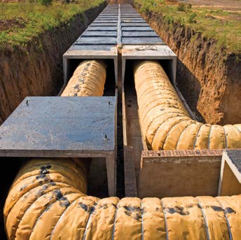 |  |  |
| Buried and road crossing pipes | Corrosion under insulation (CUI) | Pipe racks | Vertical pipes |
Guided Wave Technology
Guided wave technology is a nondestructive testing method used to locate potential degradation, such as internal or external corrosion and metal loss. While conventional UT provides localized inspection, underneath or in the vicinity of the sensor location, guided waves are able to screen the entire pipe wall, over tens of meters, from a single inspection position. Then, prove-up inspection only needs to be conducted at the specific indication position. Combined with other NDT techniques, a guided wave system will help to maximize the efficiency of a corrosion management program, without compromising data quality.
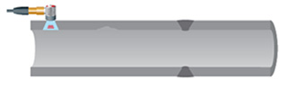 | 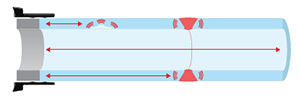 |
| Conventional UT provides localized inspection, underneath or in the vicinity of the sensor location. | Guided wave inspection allows for the entire pipe wall to be screened over tens of meters from each side of the probe collar location. |
Advantages of Guided Waves
- High productivity inspection with long-range coverage and rapid screening.
- Ability to scan pipes with limited access, such as buried, coated, insulated and through wall pipes, leading to cost reduction for excavation and insulation removal.
- 100% screening coverage of pipe wall.
- Cost effective solution for pipe integrity management programs.
- In-service inspection (no production shutdown).
UltraWave LRT System
The UltraWave LRT system excites low-frequency ultrasonic waves that propagate in the axial direction of the pipe, from both sides of the probe collar. Various factors influence the maximum inspection distance: the pipe configuration and environment, the type of fluid inside the structure, and the type of coating. The propagated torsional waves detect general variations in the total cross-sectional area of pipe, as well as changes in the material properties.
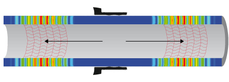
Inspection lengths range up to 91 meters (300 feet) on each side of the probe collar.
The Olympus UltraWave LRT system is a turnkey solution with all the tools and accessories required to perform efficient inspections in the field :
- Data acquisition unit with a broad frequency range, from 15 kHz to 85 kHz, and an inspection length that extends up to 182 m (600 feet) bidirectionally.
- Standard probe collar kits, covering pipe diameters from 2 in. to 24 in. OD.
- Probe collars for other diameters available upon request.
- Rugged industrial touch-screen laptop computer.
- Latest version of UltraWave LRT software with advanced features such as F-scan, Active Focusing and Synthetic Focusing (C-scan).
- Tool kit, spare parts, and user manuals.
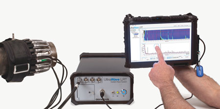
Acquisition Unit
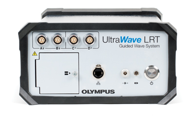
The UltraWave LRT system includes a 16-pulser acquisition unit with a frequency spectrum of 15 to 85 kHz, adjustable in 1 kHz steps for high resolution. Lower resolutions are available in the software to reduce acquisition time and data file size. Portable and battery operated, the unit is supplied with a backpack for easy on-site transportation. The system offers optimized power management with two hot-swappable batteries to maximize on-site efficiency.
Probe Collar
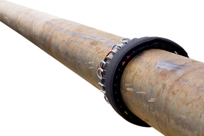
The probe modules are sealed in a molded housing for increased durability in rough environments. Their lightweight and low-profile design ensures consistent contact and stability on the pipe surface during data acquisition.
- Compact and low-profile probe module.
- Completely sealed probe module for high reliability.
- Highly resistant stainless steel wear plates.
The Olympus UltraWave LRT system has several design features that make setup straightforward and secure. All the necessary information for probe module installation is clearly displayed on the collar.
- Probe collars available for pipes as small as 2 in. OD.
- Total collar height of about 30 mm offering extremely low clearance.
- Highly flexible and portable bands for limited-access locations.
- Color-coded cables and bands for easy wiring.
- Resilient collar with easy sliding buckle, fiber-reinforced bladder, and integrated Kevlar retention strap.
Setup
Defining the scope of work for an inspection job is a critical part of the planning process for a guided wave examination. The UltraWave LRT user-friendly software provides a step-by-step wizard for entering the inspection parameters.
- Clear identification of each inspected line and its location, as well as the pipe size, material, configuration, and more.
- Illustrations, detailing the positioning and orientation of the probe collar.
- Intuitive tree control for database management.
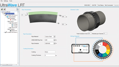
The user-friendly software facilitates the management of all relevant inspection information.
Analysis
F-Scan Color Map
Guided wave technology is a frequency-dependent detection method. The UltraWave LRT software is equipped with a unique F-scan color map that displays the entire frequency range acquired over the inspected pipe length. With this color map, selecting the optimum frequency for further analysis is fast and intuitive. A shadowed zone on the F-scan represents the low area of the power curve.
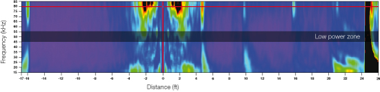
The F-scan color map displays the entire frequency range at a glance.
A-Scan Analysis
Once a frequency is selected, the corresponding A-scan is displayed and used for detailed analysis. The A-scan analysis features distance-amplitude correction (DAC) curves, reflector annotations, and an option for additional notes. Two independent sets of DAC curves can be adjusted for the forward and the reverse direction.
When an indication is tagged on the analysis graph, the software updates the pipe schematic with a pre-selected symbol. Then this information, including the user’s notes, is compiled in an indication table, which is saved for the report.
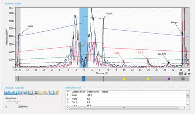
An annotation list linked to a defect table allows for a quick A-Scan analysis.
Active Focusing
The active focusing capability enhances the flaw evaluation performance by delivering concentrated energy to a specific portion of the pipe, resulting in a better signal-to-noise ratio. Once a specific distance on the pipe has been selected, the energy is then focused at eight different positions around the circumference, investigating the pipe cross-section, segment by segment. The active focusing also estimates the circumferential extent of the indication.
- Polar plot representation displays the scope of the indication from a circumferential viewpoint.
- Improved penetration power and inspection
confidence for advanced applications such as buried or heavily coated pipes. - Reduced defect false-alarm rates.
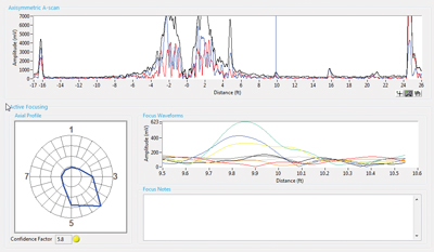
The active focusing mode delivers concentrated energy at the desired distance, and the corresponding axial profile evaluates the indication extent.
Synthetic Focusing
Synthetic focusing is a post-processing tool (offline) for advanced data analysis. A virtual image of the unrolled pipe (C-scan) is generated, based on the phase velocity of the received mode. It is performed at one selected frequency.
- Displays the entire inspected zone.
- Provides the axial position and circumferential extent of all defects.
- Unrolled pipe view (C-scan).
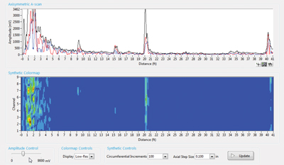
Synthetic focusing mode provides an unrolled pipe view (C-scan).
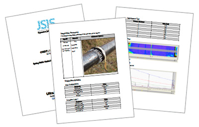
Reporting
A report automatically compiles all of the necessary inspection data into a single document. Specific data can be selected and added to the user-friendly Report Tree menu, including F-scan, Active Focusing and Synthetic Focusing views. The report is customizable with all the details related to the inspection location.
An integrated camera on the laptop allows the user to quickly import a picture of the inspected site into the report.
| Acquisition Unit Specifications | |
| Weight | 7.1 kg (16 lb) |
| Dimensions (W × H × D) | 250 mm × 150 mm × 400 mm (9.8 in. × 6 in. × 15.7 in.) |
| Environment Specifications | Storage temperature: –20 ˚C to 60 ˚C (–4 ˚F to 140 ˚F) Working temperature: 0 ˚C to 45 ˚C (32 ˚F to 113 ˚F) |
| Power | Two lithium-ion batteries and AC adaptor |
| Instrument Autonomy | 1 day of typical 8-hour shift operation |
| Standards | CE, RoHS, WEEE |
| Casing | IP54 rated |
| Batteries | |
| Battery Model | OMNI-A-BATT2 (U8760059) |
| Battery Type | Smart lithium-ion batteries |
| Pulser specifications | |
| Number of Channels | 16 |
| Pulse Type | Square wave |
| Pulse Voltage | 40–300 Vp-p |
| Mode | Pulse-Echo |
| Frequency Range | 15 kHz to 85 kHz |
| Number of Cycles | 1–10 |